Automated measurements can save you a lot of time. Now, with Analog Discovery Pro, you can automate analog signals data readout and comparison. This project shows you how to use the Analog Discovery Pro in Linux mode to automate testing the PmodAD5, an SPI-enabled ADC. Automation is accomplished using WaveForms SDK to measure analog signals going into the Pmod and SPI controls to read data out, comparing the two results.
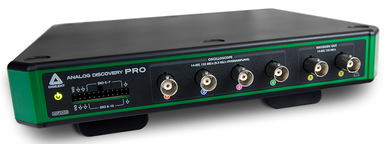
The ADP3450 and ADP3250 are the first in the line of Analog Discovery Pro devices and take the analog and digital instruments from the internationally popular Analog Discovery and turn up key functionalities to meet the growing need for professional-level home electronics test benches. At the heart of each device is a four or two-channel high-resolution oscilloscope, offering 14-bit resolution at up to 0.5 GS/s. Additionally, to meet the needs of an increasingly digital world, 16 dedicated digital channels make the Analog Discovery Pro a true mixed-signal oscilloscope. With the included digital power supply, digital outputs, two-channel arbitrary waveform generator, and two dedicated external triggers the Analog Discovery Pro come with 12 instruments ready to analyze mixed-signal systems through our free software, WaveForms.
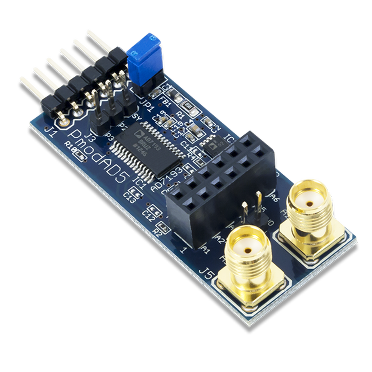 The Pmod AD5 is an analog-to-digital converter that utilizes a fourth-order sigma-delta modulator, a programmable gain array, and on-chip digital filtering, all powered by the Analog Devices AD7193. With 24 bits of resolution on up to 8 different analog input channels, users may read the highly accurate voltage measurements with an RMS noise as low as 11 nV through SPI.
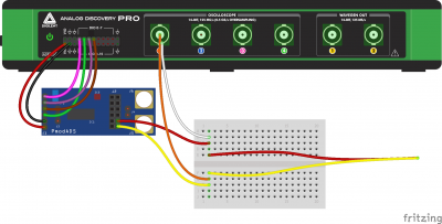
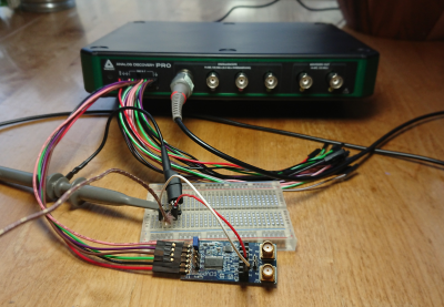
The first step is to plug the BNC connector of the scope probe into Oscilloscope Channel 1 and the MTE cable into the digital MTE connector. Connect the DIO channels, ground, and VIO from the Analog Discovery Pro to the PmodAD5 as shown in the image on the right.
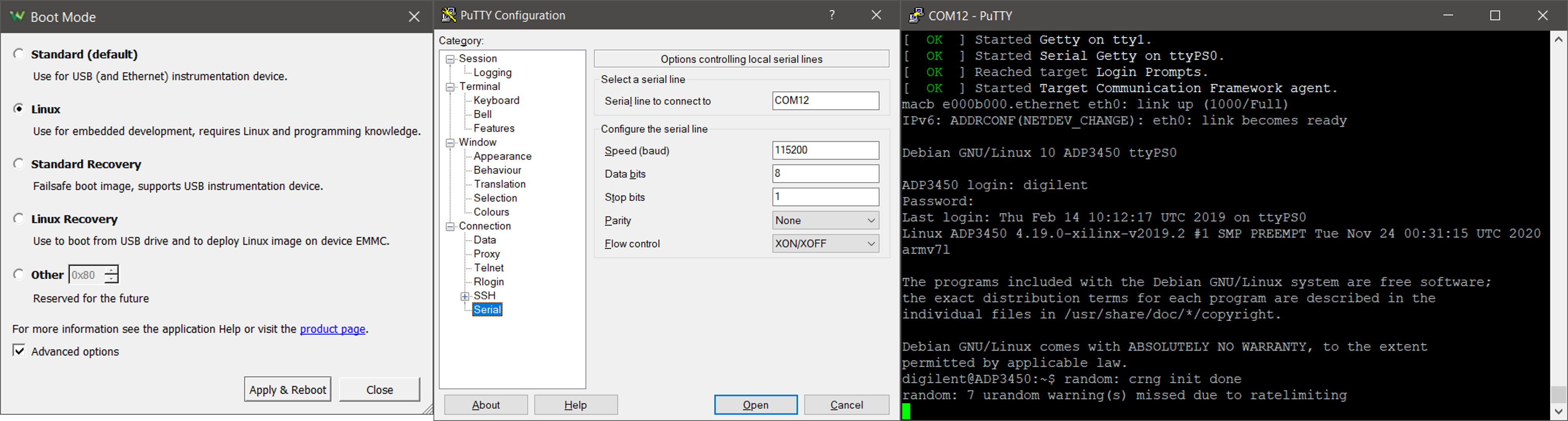
Next, configure the software setup by connecting the Analog Discovery Pro to a host computer via USB, open WaveForms, and enter Linux mode. Open a terminal emulator such as PuTTY or TeraTerm and connect to the serial port.
Test on Python
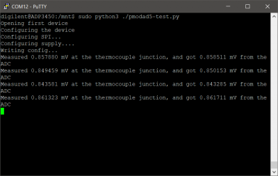
At the beginning of the Python script, the necessary modules are imported and the WaveForms dynamic library is loaded. Before using a Test and Measurement Device, it needs to be connected to the host. The Digital IO, Analog Input, and Voltage supply are initialized one after the other. The ADC is put into single conversion mode and configured to have a gain of 100, then it is calibrated. The test is started by beginning an analog acquisition to measure the voltage at the thermocouple junction. The data given by the PmodAD5 is converted into proper voltage values and the average of the acquired samples is calculated before the result is displayed on stdout.
Finally, download the project file and run the script provided on the project page. This script configures the PmodAD5 via SPI and iterates over a list of voltages used to set a DC signal from the Wavegen. It then issues a read command over SPI, records the results, and continues to the next voltage until there are none left. The results are output to the terminal upon completion.
Get the project details on the Digilent Reference Page.