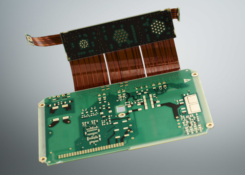
Many products connected to the IoT and flexible displays demand smaller, lighter and more cost-effective products. In these cases, a flexible circuit is a viable option. Flexible PCB material is utilized to meet challenging form-factor requirements, eliminate connectors and improve performance.
One positive aspect with flex and rigid-flex circuits is the reduction in assembly time. For rigid-flex, reduced use or elimination of connectors will also increase reliability. Customers often request a reduction in costs, time spent in assembly, fewer cables and sockets. These requirements are in many cases solved with flex and rigid-flex boards.
A huge variety
The adoption of flexible circuits is growing because it offers a huge variety for seamless interconnections, lighter weight, improved reliability, and compressed constructions. With the many manufacturing options and material choices available to prospective flex circuit users, the possibilities and processing choices are numerous.
So why do we talk so much about rigid-flex now? Consider the trends in the news: IoT is not just a buzzword tech-bloggers toss around, it’s a completely new industry where rigid-flex boards fit like French cheese and wine. With the rising possibilities IoT brings, it can come in handy to have some advice on what to consider when planning rigid-flex printed circuits.
The following are eight things to consider when planning a flex or rigid-flex board:
1. Weight reduction. The use of flexible circuits can reduce the weight of an electronic package significantly, due to the fact that they do not have reinforcements that are characteristically higher in density than unfilled polymers.
2. Decreased assembly time. Seamless integration of several rigid boards into one rigid-flex, which can be assembled and soldered as one PCB, will save time. Connectors and cables are gone, and reliability is another benefit borne out of this.
3. Purchasing cost. The purchasing cost might be higher when purchasing a rigid-flex PCB, where several pieces are connected together with flex, than purchasing each board separately. However, you do not need to buy any connectors or cables between them. And with the increased system reliability you get by not using connectors and cables, the benefit might outrun the cost.
4. Dynamic flexing or just a bend-and-stay solution. The very thin polyimide with a very thin copper foil is ideal for dynamic flexing applications. For a bend-and-stay application, a thicker or multi-layered flex can be used.
5. Heat dissipation. Heat dissipation is normally better on the flat copper tracks you find on a flexible circuit, compared to the round wire surrounded with insulation material. This makes the flexible circuit a preferred choice in areas where resistance to heat is crucial. Stack-up for improved signal integrity is also available when using reference/shielding layers. Flexible circuits are more resistant to heat than printed circuits, such as FR4.
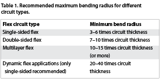
6. Bending radius. This depends on the number of layers to be bent, the thickness of the copper and the total thickness, and whether it is dynamic or just a few bends. Specific figures are available for this, shown in Table 1.
7. Materials. Most common materials are polyimide (PI), but there are also other materials available such as PET (polyester), PEN (polyethylene naphthalate), LCP (liquid crystal polymer) and others. Polyimide is the one used for products where reliability is a top priority.
Polyimide has the advantages of excellent flexibility at all temperatures, good electrical properties, good chemical resistance (except hot alkaline solutions), good tear resistance and high tensile strength, but suffers from high moisture absorption of up to 3%, is expensive compared to PEN, and its high-temperature performance is worse if used with an adhesive system.
Comparatively, PET polyester is low-cost and offers good flexibility and tear resistance, low moisture absorption, good electrical properties, and good chemical resistance. Since it is a thermoplastic, it can also be formed. However, it is not suitable for soldering and is unsuitable for extreme cold as it becomes brittle.
8. Design possibilities. Finally, and quite simply, designers benefit from an increase in design possibilities when using flexible circuits.
For more information visit https://elmatica.com/contact/